
PHONE: (847) 253-6000
TOLL FREE: (800) 52-MOTOR

Selecting BLDC Planetary Gearmotors in 2026 requires more than comparing speed, torque, and price. The correct choice begins with the machine’s real workload. A conveyor may need steady torque, while a robotic joint demands fast reversals and precise positioning. These conditions change the motor, gearbox ratio, encoder, and controller requirements.
Experienced engineers usually record duty cycle, peak load, ambient temperature, mounting limits, and expected service life. They also check backlash, radial load capacity, gear efficiency, noise, and thermal behavior. A compact 24-volt unit may fit a small device, yet overheat inside a sealed enclosure. That detail is easy to miss. It matters.
Reliable evaluation should combine manufacturer data, application testing, and independent verification. Look for clear torque curves, rated operating conditions, quality control records, and documented testing methods. Supplier support also matters when tolerances, connectors, or firmware must be customized. In 2026, feedback options such as Hall sensors, incremental encoders, and absolute encoders can strongly influence system performance. Smart integration is useful, but it should not replace basic mechanical analysis.
No selection is perfect. A spreadsheet can still hide real vibration. Prototype testing remains valuable. Measure temperature, noise, current draw, positioning error, and output backlash under actual loads. This guide explains how to compare BLDC Planetary Gearmotors with practical criteria, technical judgment, and attention to long-term reliability. The goal is not the highest specification. It is a motor-gearbox combination that performs consistently in the machine you actually build.
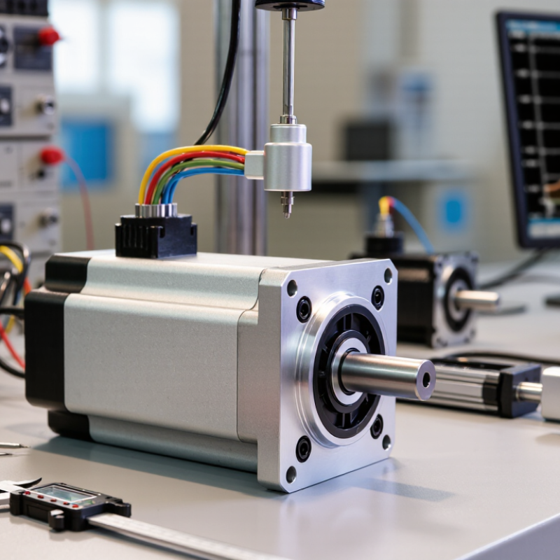
BLDC Planetary Gearmotors: Definition and Operating Principles
BLDC planetary gearmotors combine a brushless DC motor with a compact planetary gearbox. The motor converts electrical energy into controlled rotary motion. Electronic commutation replaces mechanical brushes, improving service life and reducing brush-related wear. Permanent magnets sit on the rotor, while energized stator coils create a rotating magnetic field. A controller switches these coils in sequence. Hall sensors or an encoder can provide rotor-position feedback, although sensorless control may suit simpler applications.
The gearbox increases output torque and reduces speed through three main parts: a sun gear, several planet gears, and a fixed ring gear. Planet gears rotate around the sun gear while sharing the load. This arrangement creates high torque density in a short housing. Multiple contact points also improve mechanical stability. However, efficiency depends on gear ratio, lubrication, bearing quality, and alignment. A higher ratio does not automatically mean better performance.
When choosing a gearmotor in 2026, engineers should match continuous torque, peak torque, speed, duty cycle, and available voltage. Thermal testing matters because compact housings can retain heat during repeated acceleration. A basic calculation may look correct but ignore startup load or gearbox losses. That mistake is common. Noise, backlash, shaft loading, and controller compatibility also deserve attention. Real testing under the expected load often reveals weaknesses that a datasheet cannot show.
A practical reference table for understanding construction, operating principles, performance parameters, and motor-selection criteria
| Selection Dimension | Technical Definition or Operating Principle | Typical Engineering Data | Why It Matters When Choosing |
|---|---|---|---|
| Product Definition | A BLDC planetary gearmotor combines an electronically commutated brushless DC motor with a planetary gearbox. The motor supplies rotational speed, while the gearbox increases output torque and reduces output speed. | Brushless motor + planetary reduction gearbox | This integrated design provides compact torque transmission, efficient speed reduction, and long operating life without mechanical commutator brushes. |
| BLDC Motor Principle | Electronic switching energizes the stator windings in sequence. The permanent-magnet rotor follows the rotating magnetic field generated by the stator. | Electronic commutation; commonly 3-phase construction | The controller, Hall sensors, encoder, or sensorless algorithm must be compatible with the motor’s electrical commutation method. |
| Planetary Gearbox Principle | Several planet gears rotate around a central sun gear while engaging with an outer ring gear. The carrier transfers the reduced speed and increased torque to the output shaft. | Sun gear, planet gears, ring gear, and carrier | The load is distributed across multiple gear meshes, allowing high torque density in a relatively short and compact gearbox. |
| Typical Reduction Ratio | The reduction ratio is the motor input speed divided by the gearbox output speed. Multiple planetary stages are used when a higher ratio is required. | Approximately 3:1 to 100:1; commonly 3:1 to 10:1 per stage | Select a ratio that delivers the required output speed without forcing the motor to operate continuously near its thermal or maximum-speed limit. |
| Output Speed | Output speed is approximately the motor speed divided by the reduction ratio, subject to load, slip, control settings, and gearbox efficiency. | Output speed = motor speed ÷ reduction ratio | For example, a 3,000 rpm motor with a 10:1 gearbox produces approximately 300 rpm before accounting for operating conditions. |
| Output Torque | Gearbox output torque is increased in proportion to the reduction ratio but reduced by mechanical losses. | Tout ≈ Tmotor × ratio × efficiency | Choose a gearbox with continuous and peak torque ratings above the application requirements, including acceleration and shock loads. |
| Gearbox Efficiency | Efficiency is the ratio of mechanical output power to mechanical input power. It varies with stage count, ratio, lubrication, speed, and load. | Approximately 70%–97% for typical planetary configurations | Efficiency affects available output torque, motor heating, battery runtime, and total system energy consumption. |
| Continuous Output Torque | The continuous torque rating is the torque the gearmotor can deliver during prolonged operation within specified thermal and mechanical limits. | Application-dependent; commonly from below 0.1 N·m to several hundred N·m | Compare the rating at the actual output speed and duty cycle rather than using the maximum or stall torque alone. |
| Peak or Intermittent Torque | Peak torque is the allowable short-duration output torque during acceleration, starting, reversing, or transient loading. | Often higher than continuous torque; duration must be specified | Verify peak torque duration, repetition rate, and thermal recovery time to prevent gear tooth, bearing, or winding damage. |
| Rated Voltage | The rated voltage is the nominal DC supply voltage used to define motor speed, current, and performance. | Common nominal values include 12 V, 24 V, 36 V, and 48 V DC | The selected voltage must match the controller, power supply, battery system, insulation design, and allowable current. |
| Motor Speed Range | BLDC motors are generally suited to high-speed operation, while the planetary gearbox converts that speed into a lower usable output speed. | Often approximately 1,000–10,000 rpm; application-specific | Check maximum motor speed, gearbox input speed, bearing speed, and required output speed under the full load range. |
| Control Feedback | Hall sensors provide rotor-position information for commutation. Encoders provide more detailed position and speed feedback. Sensorless control estimates rotor position from back electromotive force. | Hall sensors: six-step commutation; encoder: closed-loop positioning; sensorless: reduced hardware | Choose feedback according to starting torque, low-speed smoothness, positioning accuracy, speed regulation, and controller requirements. |
| Speed Regulation | Speed regulation describes how well the gearmotor maintains its commanded speed as load or supply voltage changes. | Depends on controller, feedback resolution, motor constants, and load inertia | Closed-loop control is generally preferred for precise speed, torque, or position requirements. |
| Backlash | Backlash is the angular movement possible at the output shaft when the direction of applied torque changes before the gear teeth fully engage. | Typical planetary gearboxes: approximately 3–30 arcmin; precision versions may be lower | Low backlash is important for robotics, indexing, servo positioning, and applications with frequent reversals. |
| Torsional Stiffness | Torsional stiffness describes the resistance of the motor and gearbox output train to angular deflection under applied torque. | Specified in N·m/rad or N·m/arcmin | Higher stiffness improves positioning response and reduces compliance in acceleration, braking, and reversing operations. |
| Radial and Axial Load | Radial load acts perpendicular to the output shaft, while axial load acts along the shaft centerline. | Must be checked against separate gearbox bearing ratings | External pulleys, sprockets, belts, and lead screws can create loads that exceed the nominal torque rating. |
| Duty Cycle | Duty cycle is the proportion of operating time under load compared with the complete operating period. | Continuous, intermittent, cyclic, or standby operation | A motor acceptable for intermittent use may overheat during continuous operation, even when the instantaneous torque is within limits. |
| Thermal Capacity | Thermal capacity is the ability of the motor and gearbox to dissipate heat generated by copper losses, iron losses, friction, and gear meshing. | Influenced by ambient temperature, mounting surface, enclosure, speed, current, and duty cycle | Calculate RMS current and RMS torque, then confirm winding temperature and gearbox temperature remain within specified limits. |
| Operating Temperature | The allowable ambient temperature range depends on winding insulation, magnets, bearings, lubricant, seals, and sensor electronics. | A common industrial range is approximately −20°C to +80°C; verify the exact design rating | High temperatures can reduce magnet strength, shorten lubricant life, increase winding resistance, and lower continuous torque. |
| Protection Rating | The enclosure protection rating indicates resistance to solid particles and water ingress according to the applicable IP classification. | Common requirements include IP40, IP54, IP65, or higher | Select the rating according to dust, washdown, humidity, oil mist, and outdoor exposure at the installation site. |
| Gear Material | Planet gears and sun gears are commonly manufactured from hardened steel, powder metal, or other engineered materials selected for load, noise, and cost. | Steel gears for higher load density; engineered materials for lower noise or light-duty use | Material, heat treatment, tooth geometry, lubrication, and manufacturing accuracy affect service life and allowable torque. |
| Noise and Vibration | Noise and vibration are affected by gear tooth accuracy, motor commutation, bearing quality, balance, speed, load, and mounting stiffness. | Measured in dB(A) and vibration velocity or acceleration | For medical, laboratory, office, and collaborative-robot applications, request noise data at the actual operating point. |
| Service Life | Service life is determined by gear tooth fatigue, bearing life, lubricant condition, winding temperature, electrical loading, and operating profile. | Often specified in operating hours or output revolutions | Use the real load spectrum, speed, temperature, starts per hour, and reversals when estimating life. |
| Electrical Compatibility | The motor must be matched with a controller that supports its voltage, phase current, Hall sequence or encoder interface, commutation angle, and braking method. | Verify phase count, winding connection, current limit, feedback type, and connector pinout | An otherwise suitable gearmotor may perform poorly or fail if the controller settings and feedback signals are incompatible. |
| Application Inertia | Reflected load inertia is the load inertia as seen by the motor through the gearbox. A reduction ratio can substantially reduce the inertia reflected to the motor. | Reflected inertia is approximately load inertia ÷ ratio² | Check the motor-to-load inertia ratio to achieve stable acceleration, deceleration, and servo control. |
| Sizing Safety Margin | A safety margin accounts for manufacturing variation, shock loads, friction changes, temperature, voltage fluctuation, and uncertain operating conditions. | A preliminary design commonly applies approximately 1.2–1.5× torque margin; higher margins may be needed for shock loads | Do not use a safety factor as a substitute for verifying continuous torque, peak torque, thermal limits, and gearbox life. |
| Recommended Selection Sequence | Define output speed and torque, calculate acceleration and duty cycle, select the reduction ratio, match voltage and controller, then verify thermal, mechanical, environmental, and life requirements. | Speed → torque → duty cycle → ratio → controller → thermal and mechanical validation | A structured process reduces the risk of selecting a gearmotor that satisfies one parameter but fails under the complete operating profile. |
Engineering note: The numerical ranges in this table are general reference values for preliminary selection. Actual performance depends on motor size, winding design, gearbox stage count, lubrication, mounting conditions, controller settings, ambient temperature, and duty cycle. Always confirm final ratings using the manufacturer’s technical datasheet and application test results.
It combines a brushless DC motor with a compact planetary gearbox. The motor creates rotary motion. The gearbox increases torque and reduces speed.
A sun gear drives several planet gears inside a fixed ring gear. The planet gears share the load. This creates high torque in a short housing.
Electronic commutation replaces mechanical brushes. This reduces brush wear and can extend service life. The motor also needs a suitable controller.
Not always. Sensorless control may suit simple applications. Hall sensors simplify position feedback. Encoders support more accurate output positioning.
Check continuous torque, peak torque, speed, voltage, and duty cycle. Include startup loads and acceleration forces. A simple calculation may miss gearbox losses.
Compact housings can retain heat during repeated acceleration. Test the motor inside its real enclosure. Watch for heat buildup during starts and holding periods.
Confirm current regulation, commutation, overcurrent protection, and thermal protection. Check peak current and voltage drops during acceleration. Cable resistance can matter.
No. Higher reduction can increase force but slow response. It may also affect efficiency, backlash, and control behavior. More reduction is not automatically better.
Include the controller, wiring, cooling, maintenance, and replacement time. Review efficiency curves and life calculations. The cheapest purchase can become expensive later.
Test a sample under the hardest realistic duty cycle. Check vibration, noise, backlash, temperature, and control stability. A clean spreadsheet can still be wrong.
BLDC Planetary Gearmotors combine the efficient, low-maintenance operation of brushless DC motors with the high torque density and compact structure of planetary gearing. This article explains how their operating principles affect output performance and introduces the key specifications used to compare options, including rated torque, peak torque, speed, power, efficiency, gear ratio, allowable radial and axial loads, noise, and thermal limits. Understanding these factors helps engineers avoid selecting a motor that is either underpowered or unnecessarily large.
The guide also shows how to match torque, speed, and gear ratios to the needs of different applications while considering acceleration, duty cycle, load variation, and available space. It reviews control methods, power-supply compatibility, and feedback requirements such as sensors or encoders for accurate positioning and speed regulation. Finally, it presents a practical 2026 selection approach that balances reliability, service life, sizing, energy use, total cost, installation requirements, and future system flexibility.